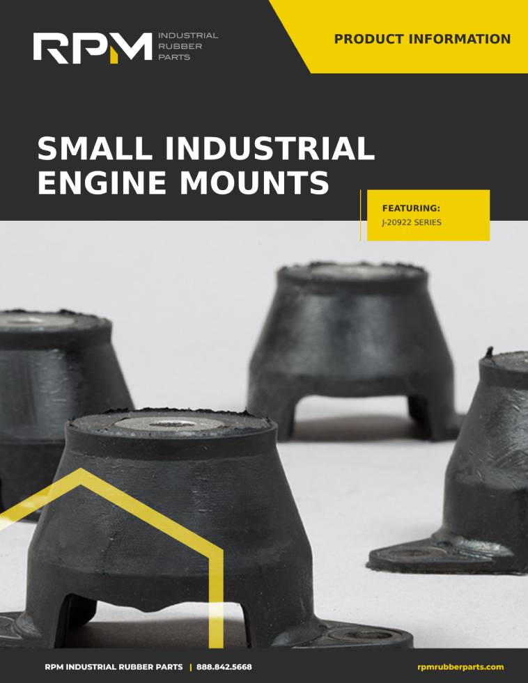
The last two posts in this series were about rubber. What isolation is and how a flexible element interrupts the path vibration takes, then how durometer sets the balance between load capacity and isolation. This one is about something most specifications never mention: the layer between the rubber and the metal.
On a rubber-to-metal mount, that layer is where the part lives or dies. The rubber can be the right compound at the right hardness, the geometry can be correct, the load can be well inside the rating, and none of it matters if the bond releases. Worse, a bond failure gives almost no warning. Compression set degrades isolation gradually over months, which at least leaves time to notice. A debond is a step change from working to not working.
So it is worth understanding what bonding actually is, how it is verified, and what it does to the way a mount carries load.
What “Bonded” Actually Means
There are three ways rubber and metal end up attached to each other, and only one of them produces a bonded mount.
The first is mechanical capture. The rubber is held in place by geometry, trapped between plates or inside a housing. Nothing is chemically joined. The second is post-cure adhesive, where a finished rubber part is glued to finished metal. Both have their uses, and neither is what the industry means by a rubber-to-metal bonded mount.
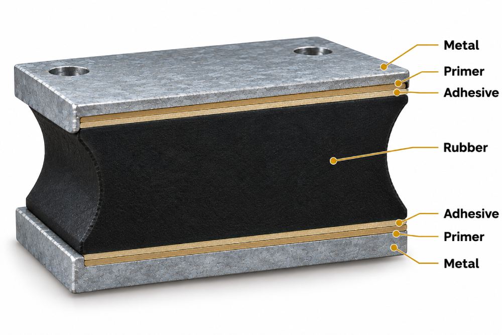
The third is a chemical bond formed during vulcanization. The metal is prepared and coated with an adhesive system, the uncured rubber is molded against it, and heat and pressure cure the rubber and the adhesive at the same time. As the elastomer crosslinks, the reactive groups in the adhesive crosslink into it. The bond is not a layer of glue holding two finished parts together. It is an interface that forms as the part itself forms, typically between about 290 and 340 degrees Fahrenheit over ten to twenty minutes depending on the geometry.
Done correctly, the result is an interface stronger than the rubber. That is the standard the process is aiming at, and it has a practical consequence: when you destroy a properly bonded part, it tears through the rubber rather than releasing at the metal.
Do you really know everything about designing with rubber parts?
Get a free and valuable resource for finding or custom designing the exact part you need.
The Bond Starts at the Metal, Not the Rubber
This is the part that surprises buyers. When a bonded mount fails at the interface, the compound is usually not the culprit. Industry experience puts the large majority of rubber-to-metal bond failures down to how the metal was prepared, not to the rubber that was molded onto it.
Preparation is a sequence, and every step is a place to lose the part:
- Degreasing. Oils, drawing compounds and machining residue have to come off completely. Anything left behind ends up under the adhesive.
- Grit blasting. The metal needs a controlled surface profile, not just a clean surface. Too smooth and there is nothing for the adhesive to key into.
- Conversion coating where appropriate. On carbon steel, a phosphate coating adds corrosion protection under the bond, which matters more in service than it does on day one.
- A short window between blasting and priming. Freshly blasted steel starts reacting with the air immediately. Parts that sit around before priming bond worse, which is why a controlled blast-to-prime window is part of a real process.
- Clean handling throughout. A bare-handed fingerprint on a prepared surface is a contaminant. Gloves are not a formality on a bonding line.
The bonding system goes on in two thin layers, a primer against the metal and an adhesive facing the rubber, each measured in fractions of a mil. That system has to suit the elastomer. What works for natural rubber is not automatically right for a peroxide-cured compound, and mismatches there are a recurring source of failures.
The takeaway for anyone specifying mounts is that the meaningful question is not only what compound the mount uses. It is what process built it.
How a Bond is Proven: ASTM D429
Rubber-to-metal adhesion has a test standard, ASTM D429, and its methods cover the common geometries. Method A pulls rubber bonded between two parallel plates straight apart. Method B peels rubber back from a metal plate at 90 degrees and is the workhorse for production quality control. Method C uses a conical specimen for parts whose shape does not suit the first two.
Here is the part worth knowing: the force number is not the whole result. Where the specimen failed matters just as much, and a test report records it. If the rubber tears while the bond holds, the process did its job, and that is the outcome the whole sequence exists to produce. If the separation runs between the rubber and the adhesive, the problem usually sits with the adhesive system or the cure. If the adhesive lets go of the metal, the problem is contamination or surface preparation. The failure tells you which step to go fix.
So a supplier who tests bonds can tell you not only that parts pass, but which failure mode they accept. That answer says more about a bonding line than a datasheet does.
What Bonding Does to the Way a Mount Carries Load
Bonding is not only about keeping the mount together. It changes the mechanics.
Rubber is effectively incompressible. Squeeze it and it does not shrink, it bulges sideways. In a bonded mount, the rubber is anchored at both faces and cannot bulge there, so it can only deform on its free surfaces. The more the geometry restrains that bulging, the stiffer the mount is in compression. This is why two bonded mounts made from the same compound at the same durometer can have very different compression spring rates. Shape does the work that hardness gets the credit for.
Shear behaves differently. When a bonded mount is loaded sideways, the rubber deforms in shear rather than trying to bulge, and shear stiffness is essentially unaffected by the shape restraint that drives compression stiffness. The practical result is that the same mount is dramatically softer in shear than in compression.
Connect that to “Vibration Isolation 101” and the consequence follows. Softer means more deflection, more deflection means a lower natural frequency, and a lower natural frequency means better isolation. Loading a mount in shear is one of the most effective ways to isolate a light load well. And it is only possible because the rubber is bonded. Unbonded rubber under a shear load slides, creeps, and eventually walks out from under the equipment.
So a bonded design gives the engineer three levers rather than one: the compound, the durometer, and the direction the load is carried. Most mounting problems that look unsolvable at a given durometer are really problems of loading the mount the wrong way.
Where Bonding Shows Up in the RPM Line
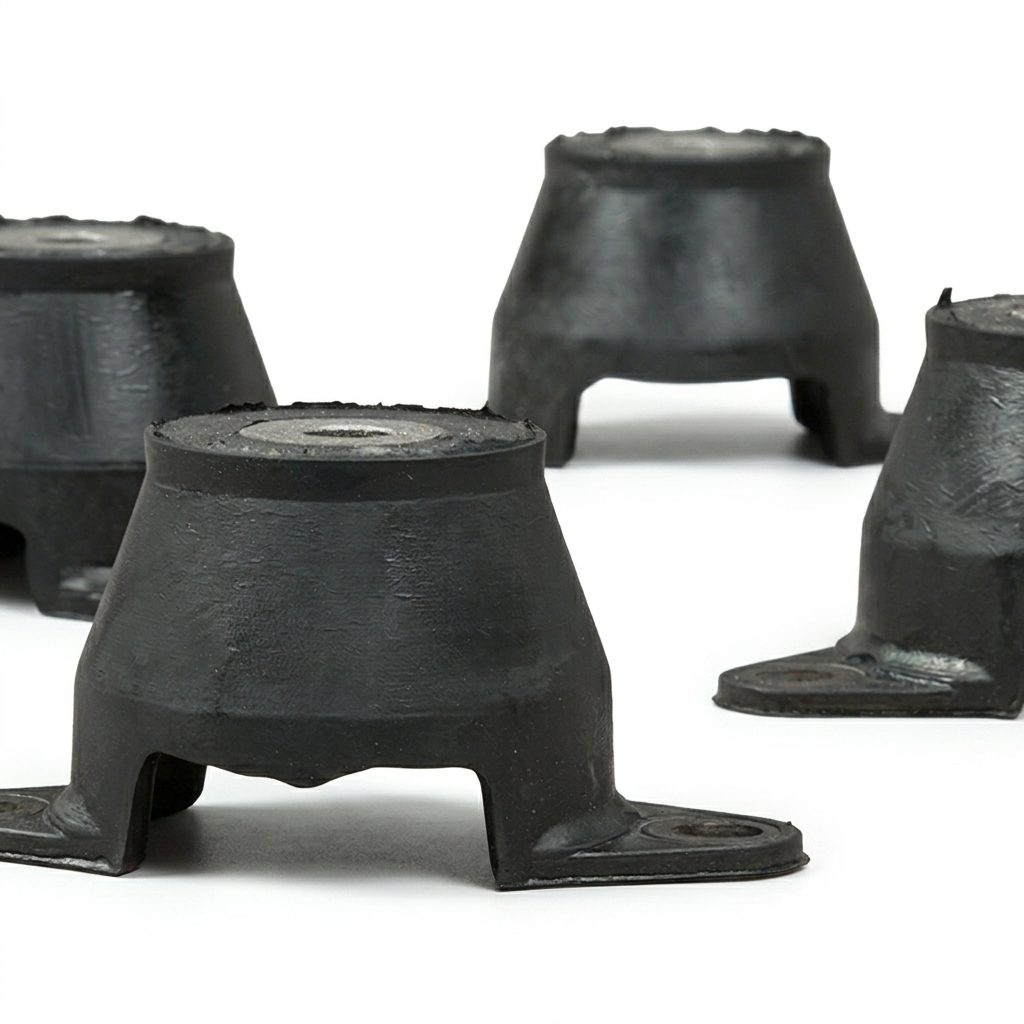
Bonded construction is not one product. It is a method that shows up differently across the vibration control line, and the families differ mainly in how the load is oriented and how much protection is designed in against overload.
- Cab Mounts. A single bolt system with overload and rebound washers, tuned to control movement under shocks and bumps while keeping ride comfort in a vehicle cab.
- Rubber Flex Sandwich Mounts. Rubber bonded between threaded plates, offered in UNC and metric thread types along with vibration feet and buffers. The low cost general purpose answer, and the one that covers most control panels, small motors, compressors and equipment feet.
- Large Shear Mounts. Unitized bonded construction in three size groups, built for high load capacity and energy control in genuinely violent service: feeders, compactors, shredders and vibratory rollers. This family is the shear principle described above, applied at scale.
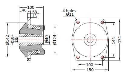
- Anti-Vibration Flange Mounts. A two-bolt flange design spanning roughly 20 kg to 5,000 kg, with rubber working in combined shear and compression and a metal top cover shielding it from oil and fuel. An integral mechanism limits equipment movement, and the fail-safe design suits mobile equipment and tight spaces. Includes square flange and marine variants.
- HVAC Neoprene Mounts. Flange mounted compression mounts, including a double deflection series, for fast economical isolation under HVAC and similar equipment. Fix the base to the surface, set the unit on top.
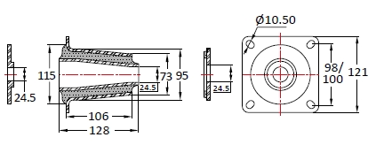
- Conical Mounts. Engineered rubber cutouts tune the ratio of horizontal to vertical stiffness, and overload and rebound washers add a fail-safe. Built for heavy loads and extreme shock in mobile and heavy duty service, in two, three and four hole configurations.
- Hydro Mounts. A rubber element paired with a hydraulic viscous damper, for applications where the damping demand runs past what rubber alone should be asked to carry. Vehicles, engines and heavy equipment.
- VCM Mounts. A single bolt design with a built-in steel cup that limits vertical movement and extends rubber life, aimed at heavy dynamic shock in off-road and construction environments.
- Safetied Bonded Tube Form Series. A permanently bonded tube form with cushioned snubbing to prevent metal-to-metal contact, isolating and protecting against shock in all directions and rated to 10 g. Used with the recommended bolt, washer and nut, the mount stays captive even after an overload failure. Engines, cabs, fuel tanks, pumps, compressors and industrial machinery across automotive, marine, rail and industrial work.
The families overlap, and more than one will usually carry a given load. The choice comes down to how the load is oriented, how much motion is acceptable, what the mounting interface looks like, and whether the application needs the mount to stay captive if the rubber ever gives up.
Fail-Safe Designs
That last consideration deserves its own paragraph, because it is designed in rather than added later. Several of the families above build in protection against the day the rubber fails. Conical and cab mounts use overload and rebound washers. Flange mounts carry an integral mechanism that limits how far the equipment can travel. The safetied tube form series goes furthest: installed with the specified hardware, the mount remains captive after an overload failure. It stops isolating, but the equipment does not go anywhere.
This matters anywhere a released machine is a safety event rather than a maintenance one: marine and mobile equipment, anything overhead, anything that moves, and anything where a mount failure would let equipment shift under load. If the application has that character, fail-safe behavior belongs in the specification rather than in the wish list.
Reading a Bond Line Before and After Installation
A bond line is visible, and it will tell you things if you look at it.
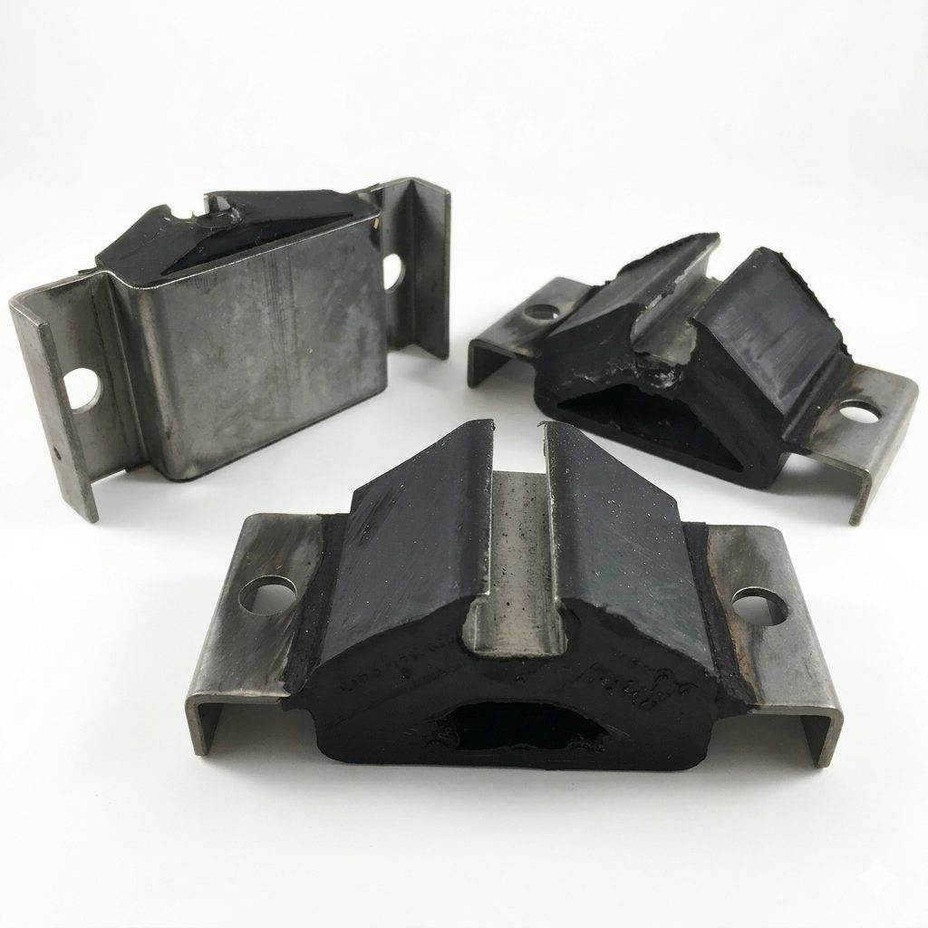
On a healthy part, the transition from rubber to metal is consistent all the way around, the fillet is even, and the adhesive is where it belongs rather than smeared across the load face. What should draw attention: gaps or lifted edges at the interface, adhesive squeeze-out onto the rubber, rust bloom right at the transition, and corrosion that appears to be creeping underneath the rubber edge. That last one is the most common field failure on outdoor and washdown equipment, because fluids and salt attack the interface as readily as they attack the rubber, and they get to work at the edge first.
It is also worth remembering how differently the two main failure modes behave. Compression set is gradual. The mount loses deflection, its natural frequency climbs, isolation quietly degrades, and there is time to catch it at inspection. A debond is not gradual. It holds, and then it does not.
What to Ask Before You Buy
Bonded mounts from two suppliers can be dimensionally identical and priced differently for reasons that only show up eighteen months into service. Five questions separate them:
- Is the rubber bonded during vulcanization, or attached after cure?
- What adhesive system is used, and is it matched to this compound?
- How is metal preparation controlled, including the window between blasting and priming?
- Is adhesion tested to ASTM D429, and what failure mode is accepted?
- Is the lot traceable back to that process data?
A supplier who can answer all five is selling a different part than one who cannot, whatever the two look like side by side.
The Three Decisions Behind Every Mount
Put this series together so far and the picture is straightforward. Durometer decides how well a mount isolates. The compound decides how long the rubber survives its environment. And the bond decides whether the assembly stays an assembly at all.
The first two get specified. The third usually gets assumed. It is the one worth asking about.
Related Resource
The Engineer’s 7-minute Guide to Rubber Molded Parts
Our free resource is a quick-reference guide to help you determine if exploring a rubber part is right for your application.